Some Ideas on Wedge Barriers You Should Know
18 might be done quicker, conveniently, and cost properly. FIG. In specific embodiments, the anchor 30 may be a steel structure including plates, light beams(e. g., I-beams ), and/or other structures that are protected within the structure 14, which may be concrete. At the surface area 12, a top side 28 of the support 30 may be at the very least partially subjected
, thereby making it possible for the attachment of the obstacle 10 to the support 30. g., threaded holes)in several light beams or plates of the anchor 30 might be revealed to the surface 12. In this way, screws 32 or other mechanical fasteners may be utilized to secure the barrier 10 to the support 30. As the barrier 10 is mounted to the surface 12 of the structure 14, collection of particles and other material under the obstacle might be minimized, and components of the bather 10 might not be subjected to listed below grade environments. As suggested by referral character 52, the lifting system 50 consists of parts disposed underneath the wedge plate 16. For instance, the parts 52 under the wedge plate 16 may include an electromechanical actuator, a camera, one or more web cam surfaces, and so forth. Furthermore, the training mechanism 50 includes a spring assembly 54
The springtime pole 58 is paired to a cam(e. g., cam 80 received FIG. 4) of the lifting mechanism 50. The springs 60 disposed regarding the spring hop over to these guys rod 58 are held in compression by spring supports 62, consisting of a taken care of springtime support 64. That is, the set spring support 64 is taken care of about the structure 14 et cetera of the bather 10.
The Only Guide for Wedge Barriers
The continuing to be pressure applied to
the cam webcam deploy release wedge plate 16 may might provided by an electromechanical actuator 84 or other actuator. The spring setting up 54 and the actuator 84(e. Wedge Barriers. g., electromechanical actuator)might run together to equate the camera and raise the wedge plate 16.
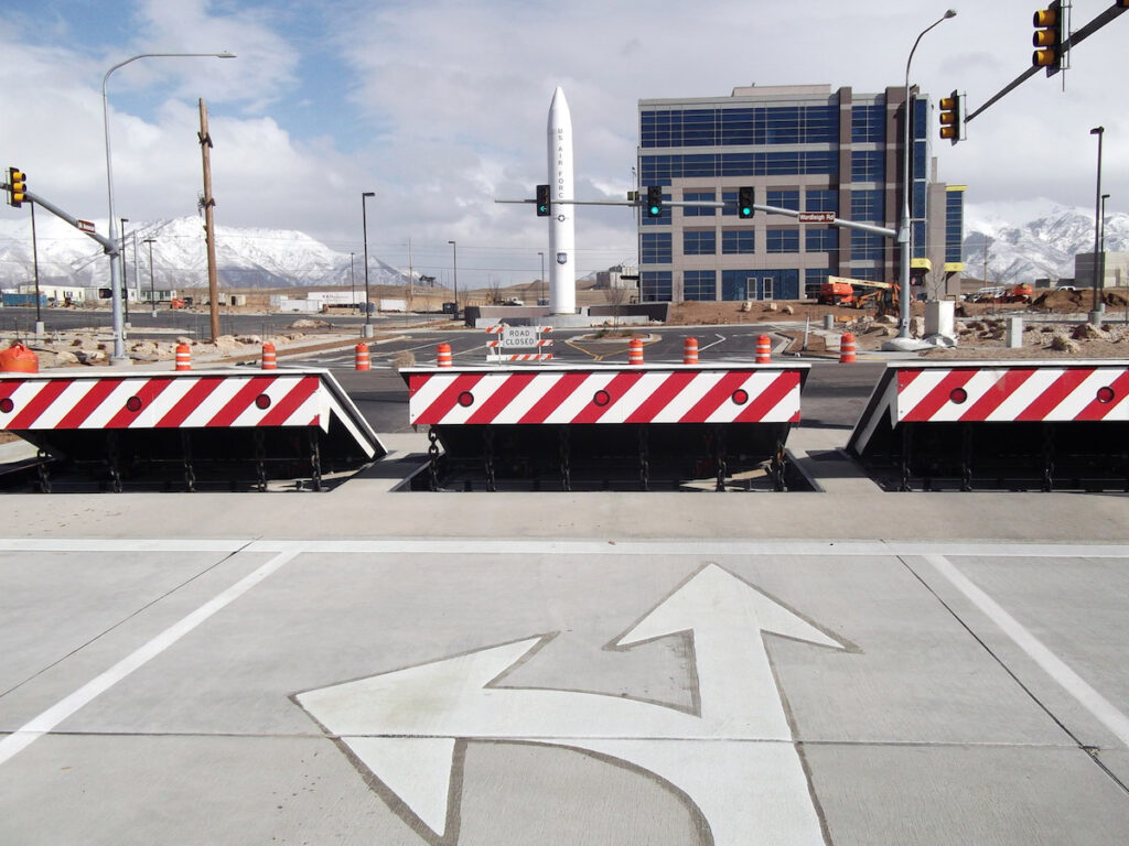
As discussed above, the springtime setting up 54 applies a continuous pressure on the web cam, while the electromechanical actuator might be controlled to exert a variable force on the webcam, thus allowing the training and decreasing( i. e., releasing and withdrawing )of the wedge plate 16. In certain embodiments, the continuous force applied by the spring setting up 54 might be adjustable. g., electromechanical actuator) is disabled. As will be appreciated, the spring assembly 54 may be covered and secured from particles or various other components by a cover plate(e. g., cover plate 68 received FIG. 4) that may be significantly flush with the elevated surface 38 of the structure 14. As mentioned above, in the deployed position, the wedge plate 16 offers to block access or travel past the obstacle 10. The obstacle 10(e. g., the wedge plate 16 )may obstruct pedestrians or automobiles from accessing a residential property or path. As gone over above, the barrier 10 is affixed to the anchor 30 secured within the structure 14,

front brackets 71. As an outcome, the affiliation settings up 72 may pivot and rotate to enable the collapse and extension of the link settings up 72 throughout retraction and deployment of the bather 10. The linkage assemblies 72 reason activity of the wedge plate 16 to be limited. For instance, if a car is traveling in the direction of the released wedge plate 16(e. As an example, in one scenario, the safety and security legs 86 might be expanded throughoutupkeep of the barrier 10. When the safety and security legs 86 are released, the security legs 86 support the weight of the wedge plate 16 versus the surface area 12. As an outcome, the training system 50 may be shut off, serviced, gotten rid of, replaced, and so forth. FIG. 5 is partial perspective view of an embodiment of the surface-mounted wedge-style barrier 10, showing the camera 80 and the camera surface areas 82 of the lifting mechanism 50. Specifically, two web cam surface areas 82, which are described as lower webcam surfaces 83, are placed listed below the camera 80. The lower webcam surfaces 83 might be taken care of to the surface 12 (e. For example, the lower webcam surfaces 83 and the installing plate 85 may form a single item that is protected to the anchor 30 by screws or various other mechanical fasteners. Furthermore, 2 web cam surface areas 82, which are referred to as top cam surfaces 87, are positioned over the camera 80 and coupled to (e. In various other embodiments, interfering layers or plates might be placed between the surface area 12 and the reduced cam surface areas 83 and/or the wedge plate 16 and the upper web cam surface areas 87 As stated over, the cam
80 translates along the camera surfaces 82 when the wedge plate 16 is raised from the pulled back position to the released setting. Additionally, as pointed out above, the springtime setting up 54 (see FIG. 3 )might give a pressure acting on the web cam 80 in the instructions 102 through spring pole 58, which may reduce the force the electromechanical actuator 84 is called for to apply to the cam 80 in order to activate and lift the wedge plate 16. 1 )to the released placement(see FIG. 4). As shown, the web cam 80 includes track wheels 104(e. g., rollers), which contact visit the site and equate along the cam surfaces 82 throughout operation.